Design for Manufacture and Assembly (DfMA) Benefit Summary
INTRODUCTION
DfMA is an approach to design that focuses on ease of manufacture and efficiency of assembly. It is a well-established approach in many sectors that are driven by the need to produce large numbers of consistently high-quality products very efficiently.
Figure 1 displays the positive impacts of opting for a DfMA solution compared to that of a traditional approach. The typical project timeline and key project milestones demonstrate the time savings when opting for DfMA. Project Feasibility becomes more efficient with the implementation of DfMA Site Suitability Surveys and standard kiosk/Motor Control Centre (MCC) layouts. These standard designs are stored in a Design Matrix, improving the reliability and detail of design whilst also enabling the tender bid to be processed more efficiently. Site preparation can be initiated sooner in the programme due to the early availability of the kiosk design layout. Off-site manufacture provides significant benefits due to the positive impacts on safety, due to the reduced number of operatives required on site. Delivery is also optimised, with DfMA meaning only a single delivery to site is required, again significantly reducing the amount of time and number of operatives required on site.
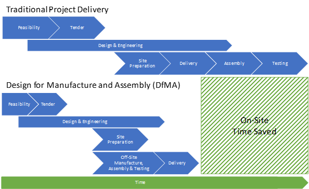
Figure 1 Impact on Programme by utilising a DfMA Solution compared to Traditional Project Delivery
FEASIBILITY & TENDER STAGE
Opting for a DfMA solution enables engagement with a single sub-contractor on a project to provide the steel base floor, decking, GRP kiosk, kiosk services, MCC and control panels as a single assembly. With each of the three DfMA standard designs being incorporated into a Design Matrix, to be used alongside the project detailed design documentation, this allows the single sub-contractor to significantly reduce the tender bid preparation time.
Determining the suitability of a DfMA solution should be carried out on a per project basis. This will be completed by a combination of physical and digital surveying in the form of 3D Laser Scanning and where required drone surveys. A 3D digital model will allow engineers to import one of the three standard DfMA designs and efficiently determine its suitability considering: access routes, offloading areas and final install location.
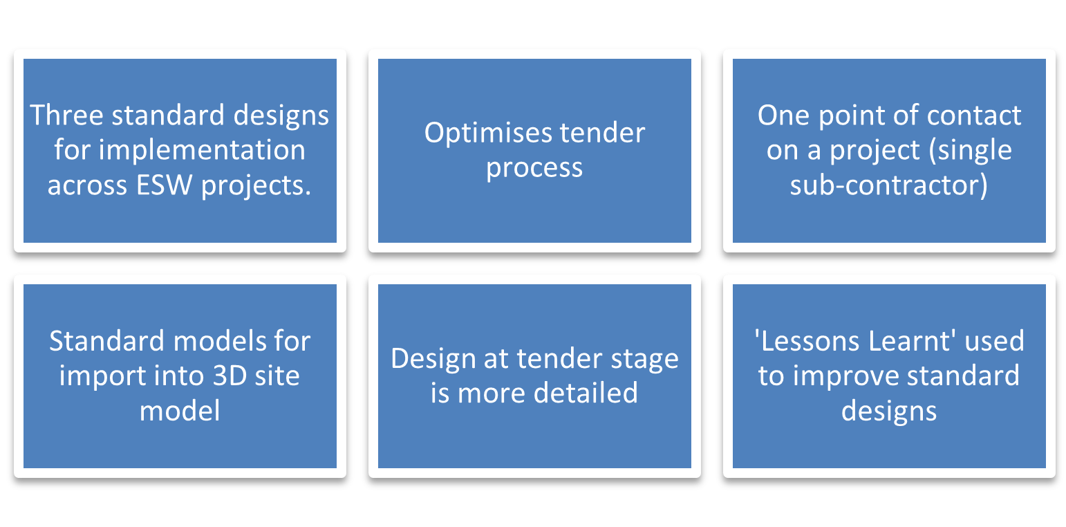
Figure 2 Feasibility & Tender Stage Benefits
DESIGN & ENGINEERING
DfMA will optimise the design and focus on ease of manufacture and efficiency of assembly. Firstly, MCC General Arrangements have been developed with a focus on standardising tiers. By having standard MCC tiers for incomers, feeders, functional devices and PLC/ICA sections, this enables efficient repeatability and ensures a consistent and familiar standard is delivered. The MCC General Arrangements include for front access cabled assemblies (these can be installed with rear face up against kiosk wall) and front & rear access fault rated assemblies. From the selection of MCC layouts, three standard GRP kiosk sizes have been developed:
• GRP Kiosk Standard Design 1 – 5200mm x 2550mm x 2800mm (L x W x H).
• GRP Kiosk Standard Design 2 – 6300mm x 3500mm x 2800mm (L x W x H).
• GRP Kiosk Standard Design 3 – 7600mm x 3500mm x 2800mm (L x W x H).
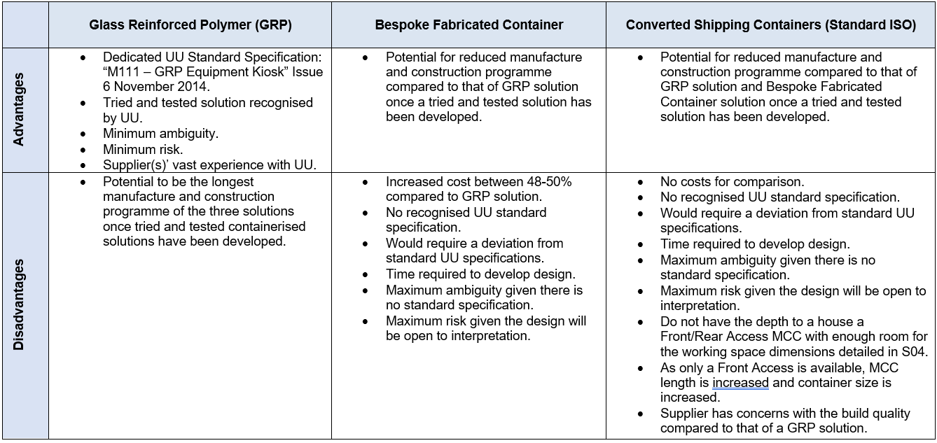
For completeness, an exercise has been conducted which compares the GRP kiosk solution to that of either a bespoke fabricated container or converted shipping container (standard ISO). A GRP kiosk solution is highly favourable and offers considerable advantages and therefore is the only solution used for the standard designs.
The proposal includes for an option to raise the GRP kiosk onto fabricated galvanised steel legs (stilts proposed at 1000mm high), significantly improving the accessibility to the underside of the kiosk. By raising the kiosk this also acts as an effective flood protection measure. GRP or mesh panels, along with access panel are to be fitted to only allow authorised access to the underside of the kiosk. The stilts option allows the use of a flat concrete base, as appose to a concrete trench base, which decreases the civil cost and complexity of the construction.
With the three typical designs in place, detailed design and engineering can be optimised by enabling the use of template drawings and documentation i.e. kiosk layout drawings, MCC general arrangements, MCC schematic diagrams, kiosk building services drawings, Bill of Materials (BOM’s), FAT & SAT documentation and Operation and Maintenance manuals (O&M’s).
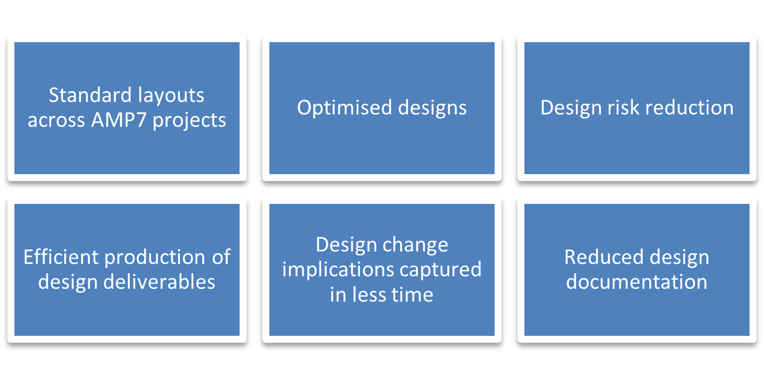
Figure 3 Design & Engineering Stage Benefits
SITE PREPARATION
DfMA will significantly reduce the construction programme on-site, due to the steel base floor, decking, GRP kiosk, kiosk services, MCC, and control panels all included as part of the off-site assembly. Traditionally, each of these services are individual line items on the construction programme and covered by a separate subcontract. By opting for one of the three standard DfMA designs, layouts are determined more efficiently allowing site preparation to begin earlier in the programme compared to a traditional approach.
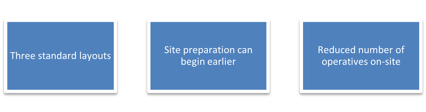
Figure 4 Site Preparation Benefits
OFF-SITE MANUFACTURE, ASSEMBLY & TESTING
Taking much of the construction activity off-site and into a controlled, ISO certified manufacturing facility allows for consistent high standards. The highly automated approach in manufacturing the GRP kiosk and steel base enhances quality and efficiency at every stage – both in the products themselves, which are repeatedly honed to support optimum performance, and in the production process. This optimisation process can also improve the sustainability credentials of raw materials used.
The MCC and services are installed into the GRP kiosk onto a pre-drilled steel base. The busbar jointing, interconnecting and external cabling to local kiosk service instruments are all installed, tested and witness tested at the off-site manufacturing facility prior to acceptance by the main contractor.
Reliability of the Factory Acceptance Test (FAT) is improved, due to the MCC and kiosk services being fully installed. With a traditional approach, following a FAT, an MCC is disassembled, wrapped and transported to site where it is then reassembled. Certain aspects of the Site Acceptance Test (SAT) are no longer required with a DfMA solution, such as re-installing busbar fish plates, interconnecting wiring and carrying out flash testing, all reducing time on-site.
The most important benefit of DfMA is safety. By removing construction activities from the site and placing them in a controlled factory environment there is a significant positive impact on safety.
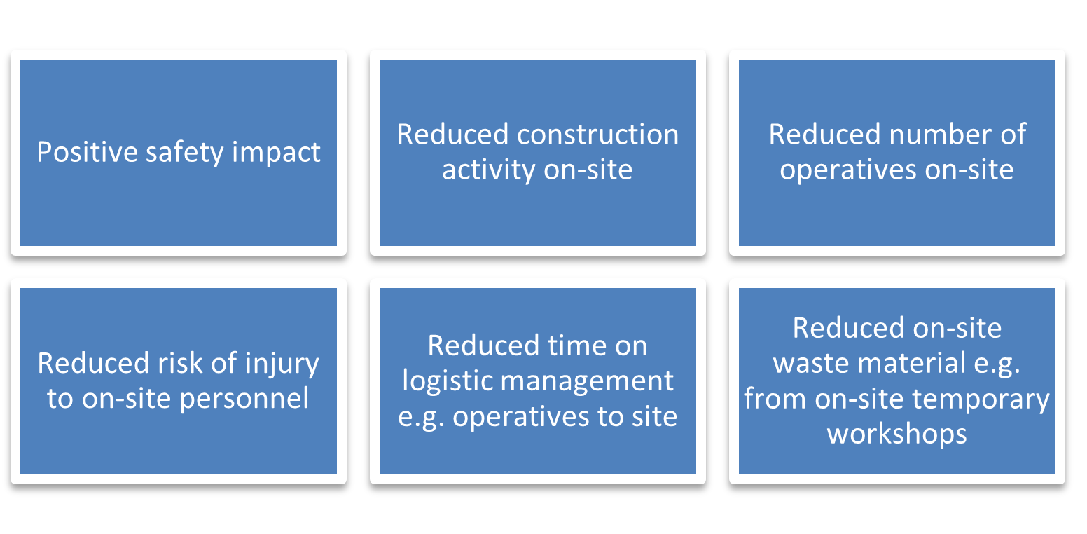
Figure 5 Off-Site Manufacture, Assembly & Testing Benefits
DELIVERY
A tried and tested delivery of the DfMA in a single assembly is cost-efficient and has a reduced carbon footprint to that of a traditional approach. Once on-site, the assembly can be taken straight off the trailer and installed immediately, reducing the need for large lay-down areas. Many of the components are large so specialist crane hire companies are utilised where necessary. A traditional project delivery approach can include 420 working hours on site, whereas the DfMA solution reduces this to just 48 working hours on site. The working hours are mainly logistical; Driver, Crane Operator, Banksmen and Supervision, with work being carried out at a reduced risk to personnel.
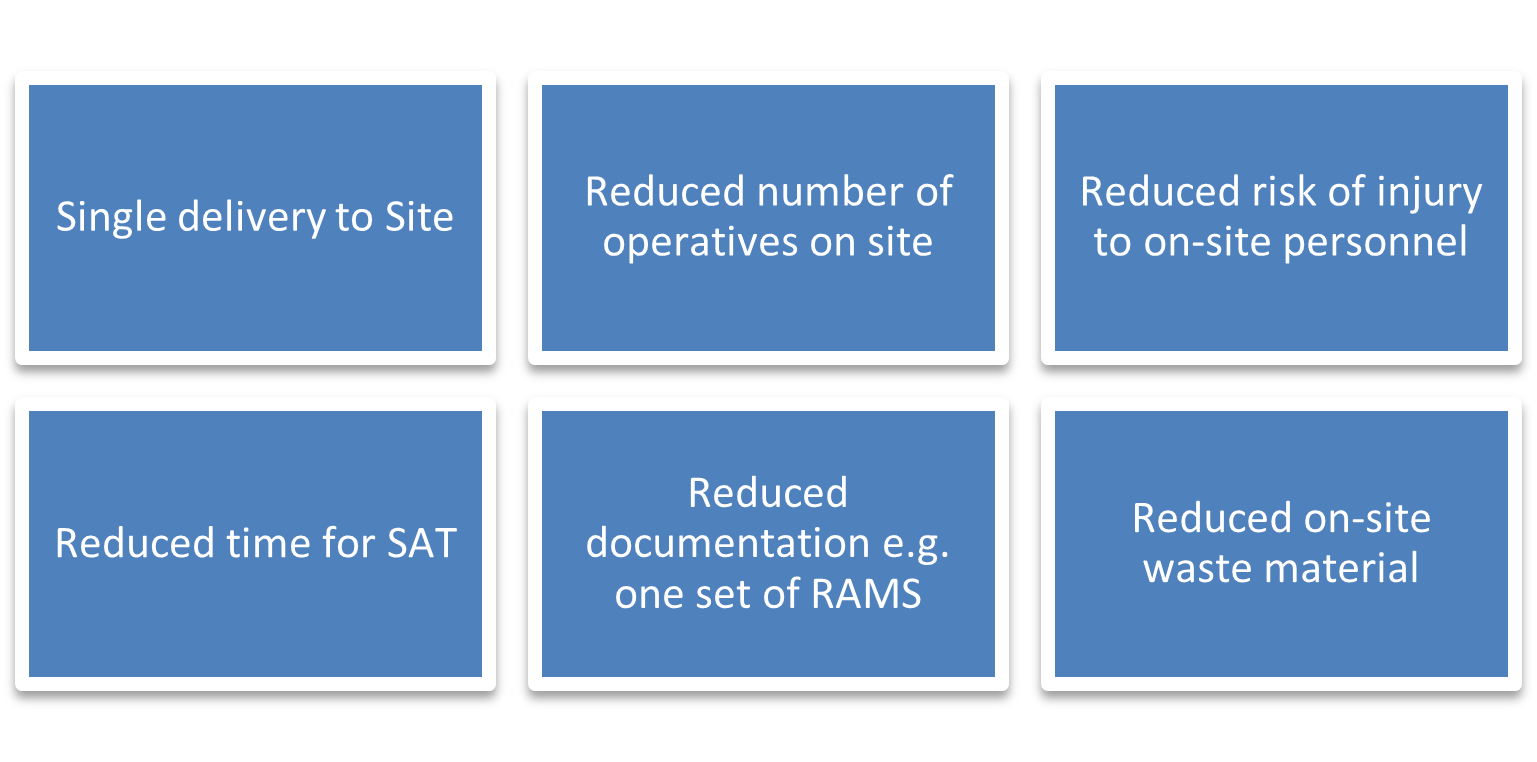
Figure 6 Delivery Stage Benefits
DFMA SUITABILITY FLOW DIAGRAM
The flow diagram shall be used to determine the suitability of DfMA for a project.
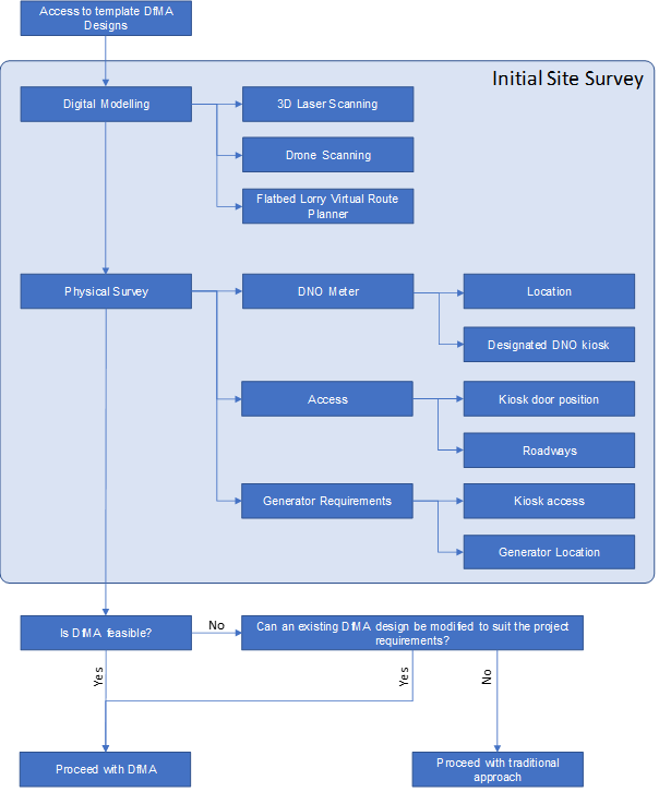
Figure 7 DfMA Suitability Flow Diagram
GRP KIOSK & CONTAINERISED SOLUTION COMPARISON
CIVIL ACTIVITY COST COMPARISON
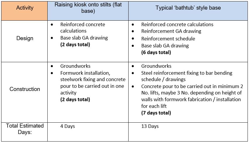
Opting for raising the kiosk onto stilts allows for the provision of a simple ‘flat’ concrete slab which reduces the design and construction time required on a project.
For a typical ‘bathtub’ style base solution, this comprises of a low-level slab, vertical walls and a ground ‘apron’ slab. Steel supports are also required to support the MCC’s and flooring.
A comparison of the activities required for opting to raise the kiosk onto stilts, and for a typical ‘bathtub’ style base solution are shown below: